

 01:39
01:39
 technoclub

The 12F675 does not have a built in USART that you can use for a PIC serial port so you have to use a software USART which you can download from this page.
Adding a pic serial port connection to the circuit gives you scope for much more interesting projects as you can collect data from the ADC (inputs) or comparator or external infrared receiver module etc. and transmit it to a PC.
This tutorial covers creating the software Transmitter (TX) part of the USART as this is the most useful part of a USART and you don't really need the receiver unless you want to control the microcontroller via a serial terminal such as Hyperterminal.
Note: The previous two tutorial pages indirectly cover the most important job in using microcontrollers i.e. input and output. Here's a summary of I/O port usage:
Sidebar
I/O Port usage summary
PORT register : TRISIO - The port direction register.
You can reset bits (low) to define port pins as outputs.
You can set bits (high) to define port pins as inputs.
PORT register : GPIO - The input/output register.
You write to this register to set output pins high or low.
You read from this register to read the current value input pins.
All of these actions were used in the previous two tutorial pages and the all work using bit values:
TRISIO = 0x01; sets bit 0 of TRISIO all the rest zero.
TRISIO = 0x04; sets bit 2 of TRISIO all the rest zero.
GPIO = 0x01; sets bit 0 of GPIO all the rest zero.
GPIO = 0x04; sets bit 2 of GPIO all the rest zero.
Note: In other PIC devices ports are labeled alphabetically and they do not use the GPIO name instead they use the text 'PORT'. So the first port is labeled PORTA the next PORTB etc. Corresponding port direction registers are TRISA and TRISB. You can use them in exactly the same way as GPIO and TRISIO.
PIC Serial Port : Software TX part
The code for the TX part of the USART is simplified in that it generates 10 bits of serial data with no parity bit.
The basic PIC Serial port configuration for the TX software is:
| Bits per second (BAUD) | 2400 |
| Number of bits | 8 |
| Parity | None |
| Stop bits | 1 |
| Flow control | None |
Note: To review how the RS232 pic serial port works click here.
Since each bit takes 1/2400 seconds the total time to transmit a digit is 4.16ms.
Note: The bit timing won't be exact as the PIC chip runs at 4MHz but it will be good enough for bench top use.
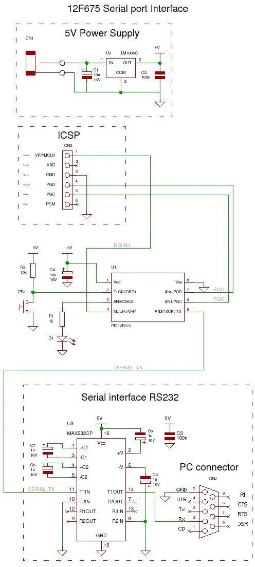
Circuit
The circuit uses the standard MAX232 level translator chip but you could use an SP202ECP which has identical pin out (and is cheaper!) and lets you use 100nF capacitors instead of electrolytic ones.
Connect the ground and transmit output to a serial port connector as shown and to a serial cable from it to the PC and it's ready to go.
For setting up hyperterminal click here.
Solderless breadboard
Add the MAX232 Chip and capacitors.

Circuit diagram
Again the pic serial port circuit is easier to see on a schematic.
Software
PIC Serial Port Operation
The code flashes the LED 3 times then repeats a message to the serial port.
The following code is part of the pic serial port transmitter:
| void _Soft_USART_Write(unsigned short chr) { unsigned short mask=1,i; unsigned int data; data = chr << 1; data &= ~0x0001; // START bit (=0). // 10 output bits for (i=0;i<9;i++) { // lsb 1st 8 bits if (mask & data) { asm {CLRW} SU_set; // output low for logic 1 } else { SU_res;// output high for logic 0 asm {CLRW} } mask <<=1; delay_us(395); // 2400 simulate to calibrate the loop. } SU_set; // stop bit delay_us(417); // 2400 } |
The character to transmit is shifted left one bit into the data variable which acts a serial shift register.
Using 'data' in this way lets the routine evaluate in a constant time without having to check an index to do a different action so for higher (more critical) speeds it works better.
The stop bit (10th bit) is a delay with the output set high.
Note: You need to calibrate the loop by timing from SU_Set to the next SU_set or SU_res if you change the baud rate.
Note: The advantage of using the hard coded timing is that the routine only takes up about 90 words.
PIC Serial Port: OSCCAL
The project relies on the accuracy of the oscillator to accurately generate the bit timings for the USART and for this you need to set the OSCCAL value.
This register changes the oscillation frequency when you write to it
OSCCAL settings
| Maximum frequency | 0xFF |
| Middle frequency | 0x80 |
| Minimum frequency | 0x00 |
Only the upper six bits are used as the calibration bits so values must be different by 4 to change to the next OSCCAL setting e.g. values 32,33,34 and 35 would give the same frequency setting.
Microchip calibrates the 12F675 microcontroller and places a calibration value at address 0x3FF. This is a RETLW instruction that returns a value when CALLed this is the value to use in the OSCCAL register.
Note: You have to use the calibration value it is not set automatically.
The code the data sheet suggests you use to set the calibration value into the OSCCAL register is :
| bsf STATUS, RP0 | ; Bank 1 |
| call 0x3ff | ; Get the cal value |
| movwf OSCCAL | ; Calibrate |
| bcf STATUS, RP0 | ; Bank 0 |
All this does is call the location that contains the RETLW value which then returns the calibration value. This assembler code is packaged into the get_set_osc_cal() routine and does the OSCCAL setting for you.
Recovering lost calibration
If you loose the calibration value then you'll need to re-calibrate - the best way is to set the internal clock at an output pin (Fosc/4) using the chip settings so you will be looking for 1MHz at the clock out pin.
Use a frequency counter to measure the output. Change the OSCCAL value until you find the one closest to 1MHz.
To get the value back into the 12F675 use ICPROG and put the hex code RETLW instruction at address 0x3FF. The first byte of the instruction is 0x34 and the second is the value returned so for a calibration value of 0x20 you would put:
0x3420 at address 0x3FF
Re-program the chip.


0 comments:
Post a Comment