

 01:37
01:37
 technoclub

If you are looking for information on general RS232 use then these rules can act as guidance but you will need to understand more about DCE (data communication equipment) and DTE (Data Terminal Equipment), all the handshaking and all the types of cable for your system. Basically there are too many - so looking at the following information could help you get a handle on the simplest configuration to show you that in fact RS232 does work.
RS232 can actually work well but a lot of software requires all the handshake signals to be in place and this is why it can be so frustrating - miss one out or connect a single wire wrongly and it will just sit there doing absolutely nothing.
Rule 1 : Keep it simple.
RS232 is only difficult if you try to use all the facilities that the standard provides. You really don't need to consider all the signals when using RS232 on the bench (for simple communication between your hardware and a PC) i.e. to make RS232 work over a few metres.
If you want to make RS232 work over long distances then you must use all the signals including handshake signals as these ensure correct operation. For 1-3 metres I only ever use the following:
- TXD Transmit data
- RXD Receive data
- GND Ground
These work for speeds of 9600 baud and beyond. You can test how far beyond by experimenting with the settings in the PIC program and PC software.
Rule 2: Use a straight through cable.
This is a cable where pin 1 connects to pin 1 at the other end, pin 2 connects to pin 2 at the other end etc.
There are two cable types:
- Straight through - also known as modem.
- Cross over - also known as null modem.
Note: Signals that are crossed over for a null modem cable are (TX,RX) and handshaking signals (RTS,CTS) and (DSR,DTR).
If you don't know what cable type you have then use a multimeter to test on its buzz setting. To make sure you don't drop everything on the floor stick a piece of wire in the female connector and wrap the other end of the wire around the multimeter probe - then you can concentrate on probing the pin in the male connector. To keep things simple use a straight through cable.
Note: Serial cables are never marked as null modem or modem - they all look the same!
The key to getting an RS232 system to work is knowing exactly what cable you have and its. Using a straight through cable you don't need to worry about Modem / Null modem cables and this eliminates a source of confusion.

Rule 3 : Crossover at your dev. board.
You can not make the crossover at the PC end as you just plug the serial cable into the PC - and that's fine. At this point you have direct connections from the Serial connector at the back of the PC all the way to your development board.
So you know exactly where you are - all connections to the development board are straight through from the PC. The final step is to make the cross over on the board.
The schematic below shows a development board with a serial connection to/from the PC that lets RS232 work between a microcontroller and the PC.
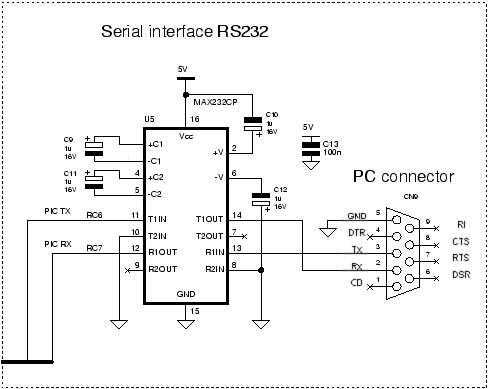
I have labeled the serial connector with the connections located at the PC - this makes it easier to visualize the whole system.
You can think of the PC and cable as one unit connecting directly to the development board and you do not need to worry about null modem cables, crossover cables, gender changers, cross over boxes etc. You only need to concentrate on the schematic with the PC serial port as an extension of the schematic.
All you do next is to connect the serial connector labeled TX (which is the serial input to the development board from the PC) to the receiver on your development board (labeled R1IN). Similarly connect T1OUT (which is the serial output from the development board) to the PC Serial port labeled RX. This makes the cross-over on your board. Next connect the grounds together (GND and 0 volts).
Rule 4 : Use identical settings at each end.
In each program there will be a setting that defines the usage of the bits transmitted between the PC and the microcontroller. To make RS232 work these settings must be identical. As a starting point use the followingsettings at each end.
| Bits per second (BAUD) | 9600 |
| Number of bits | 8 |
| Parity | None |
| Stop bits | 1 |
| Flow control | None |
If you want to change anything just change one thing at a time but again keep the same value(s) in both bits of software.
These settings are standard settings
Hyperterminal settings
In Windows you can find Hyperterminal (an accessory program) by navigating from the start menu (in windows XP):
Start->All Programs->Accessories->Communications->Hyperterminal
The following start dialog is shown (I have entered the name PIC to identify the session):

Hit OK and you are shown the connection dialog.

Hit Cancel for this dialog as you don't want to dial out.
Now from the main menu in Hyperterminal Hit File->Properties

Select the 'Connect using' drop down menu(in the middle) and select the serial port you want to use e.g. COM1.

Then hit the 'Configure' button underneath.

Phew! - got there at last - Now set the parameters as shown previously.
Rule 5 : Check your connectors before building a pcb.
A big source of confusion in making RS232 work is the connector gender (male or female). Usually a pcb designer is given a diagram that does not specify the gender of the part - and uses the one that was used last time. When it comes to building the board the connections are mirrored (male and female connectors are mirrors of each other) and you have to hand wire theconnection.
To ensure that this does not happen always lay out all the parts before finishing the schematic so that you ensure the correct gender ofconnections from one end of the system to the other.
Getting the gender of the connections is essential so double and even triple check the parts so that you know in your head which way to connect up the system.
Now drive the PIC micro using your USART code.
Other reasons that the RS232 may not work
If you are writing code on the PC the serial ports are really fussy about whatconnections are made to the serial port and require looped back signalsunless care is taken to program the chips in the PC so that they do not require loop backed signals. It is best just to use known working programs such as Hyperterminal.
Note: Loop back means faking the signals at one end - DTS is connected to RTS and DTR is connected to DSR (at the same end) - sometimes you need to control CD as well.
Another reason for RS232 not to work is if you use equipment that is powered by the serial port. Laptops are optimized for power saving so they give out the minimum power (lower volts and current).
Another possibility for RS232 not to work is voltage level sensing. Levels detected by the serial chip in the PC may not allow detection of the signal.
Newer serial port chip in the PC detect voltages below 3V (and above -3V) as a 'one' but older chips will not report it since the RS232 standard defines this voltage range as undetermined. For these older chips the voltage for a 'one' (mark) must be lower than -3V and for a 'zero' (space) must be higher than 3V. The ±3V indeterminate area gives the RS232 system immunity to noise and this allows the system to work in an electrically noisy environment but sacrificing the noise immunity means that it is easier to interface using standard CMOS logic levels (0,5V).
The only way to find out if your system works with (0,5V) logic levels is to test it - which is a pain (and what if you change it later). So it is just much easier to use a level translator chip such as a MAX232.
So does RS232 work ? - If you follow these guidelines then RS232 will work.


0 comments:
Post a Comment