

 04:04
04:04
 technoclub

By interfacing different types of sensors with our MCU we can sense the environment and take decisions, in this way we can create "smart" applications. There are wide variety of sensors available. In this tutorial we will learn about a popular sensor LM35 which is precision centigrade temperature sensor. It can be used to measure temperature with accuracy of 0.5 degree centigrade. We can interface it easily with AVR MCUs and can create thermometers, temperature controller, fire alarms etc.
LM35
LM35 by National Semiconductor is a popular and low cost temperature sensor. It is also easily available. It has three pins as follows. |
Fig - LM35 Pin Configuration |
10MilliVolts per degree centigrade.
So if the output is 310 mV then temperature is 31 degree C. To make this project you should be familiar with the ADC of AVRs and also using seven segment displays. Please refer to following articles.
- Using the ADC of AVRs
- Using Seven Segment Displays.
- Using Seven Segment Displays in Multiplexed Mode.
5/1024 = 5mV approx
So if ADCs result corresponds to 5mV i.e. if ADC reading is 10 it means
10 x 5mV = 50mV
You can get read the value of any ADC channel using the function
ReadADC(ch);
Where ch is channel number (0-5) in case of ATmega8. If you have connected the LM35's out put to ADC channel 0 then call
adc_value = ReadADC(0)
this will store the current ADC reading in variable adc_value. The data type of adc_value should be int as ADC value can range from 0-1023.
As we saw ADC results are in factor of 5mV and for 1 degree C the output of LM35 is 10mV, So 2 units of ADC = 1 degree.
So to get the temperature we divide the adc_value by to
temperature = adc_value/2;
Finally you can display this value in either the 7 segment displays by using the Print() function we developed in last tutorial or you can display it in LCD Module. To know how to display integer in 7 segment displays
Program (AVR GCC)
#include <avr/io.h>
#include <avr/interrupt.h>

#include <util/delay_basic.h>


#define SEVEN_SEGMENT_PORT PORTD
#define SEVEN_SEGMENT_DDR DDRD

uint8_t digits[3];   //Holds the digits for 3 displays


void SevenSegment(uint8_t n,uint8_t dp)
{
/*
This function writes a digits given by n to the display
the decimal point is displayed if dp=1

Note:
n must be less than 9
*/
   if(n<10)
   {
      switch (n)
      {
         case 0:
         SEVEN_SEGMENT_PORT=0b00000011;
         break;

         case 1:
         SEVEN_SEGMENT_PORT=0b10011111;
         break;

         case 2:
         SEVEN_SEGMENT_PORT=0b00100101;
         break;

         case 3:
         SEVEN_SEGMENT_PORT=0b00001101;
         break;

         case 4:
         SEVEN_SEGMENT_PORT=0b10011001;
         break;

         case 5:
         SEVEN_SEGMENT_PORT=0b01001001;
         break;

         case 6:
         SEVEN_SEGMENT_PORT=0b01000001;
         break;

         case 7:
         SEVEN_SEGMENT_PORT=0b00011111;
         break;

         case 8:
         SEVEN_SEGMENT_PORT=0b00000001;
         break;

         case 9:
         SEVEN_SEGMENT_PORT=0b00001001;
         break;
      }
      if(dp)
      {
         //if decimal point should be displayed

         //make 0th bit Low
         SEVEN_SEGMENT_PORT&=0b11111110;
      }
   }
   else
   {
      //This symbol on display tells that n was greater than 9
      //so display can't handle it

      SEVEN_SEGMENT_PORT=0b11111101;
   }
}

void Wait()
{
   uint8_t i;
   for(i=0;i<10;i++)
   {
      _delay_loop_2(0);
   }
}

void Print(uint16_t num)
{
   uint8_t i=0;
   uint8_t j;
   if(num>999) return;


   while(num)
   {
      digits[i]=num%10;
      i++;

      num=num/10;
   }
   for(j=i;j<3;j++) digits[j]=0;
}


void InitADC()
{
ADMUX=(1<<REFS0);// For Aref=AVcc;
ADCSRA=(1<<ADEN)|(7<<ADPS0);
}

uint16_t ReadADC(uint8_t ch)
{
   //Select ADC Channel ch must be 0-7
   ch=ch&0b00000111;
   ADMUX|=ch;

   //Start Single conversion

   ADCSRA|=(1<<ADSC);

   //Wait for conversion to complete
   while(!(ADCSRA & (1<<ADIF)));

   //Clear ADIF by writing one to it
   ADCSRA|=(1<<ADIF);

   return(ADC);
}


void main()
{
   uint16_t adc_value;
   uint8_t t;
   // Prescaler = FCPU/1024
   TCCR0|=(1<<CS02);

   //Enable Overflow Interrupt Enable
   TIMSK|=(1<<TOIE0);

   //Initialize Counter

   TCNT0=0;

   //Port C[2,1,0] as out put
   DDRB|=0b00000111;

   PORTB=0b00000110;

   //Port D
   SEVEN_SEGMENT_DDR=0XFF;

   //Turn off all segments

   SEVEN_SEGMENT_PORT=0XFF;

   //Enable Global Interrupts
   sei();

   //Enable ADC
   InitADC();

   //Infinite loop
   while(1)
   {
      //Read ADC

      adc_value=ReadADC(0);

      //Convert to degree Centrigrade
      t=adc_value/2;

      //Print to display
      Print(t);

      //Wait some time
      Wait();

   }
}

ISR(TIMER0_OVF_vect)
{
   static uint8_t i=0;
   if(i==2)
   {
      i=0;
   }
   else

   {
      i++;
   }
   PORTB=~(1<<i);
   SevenSegment(digits[i],0);

}
Hardware
The hardware of the project :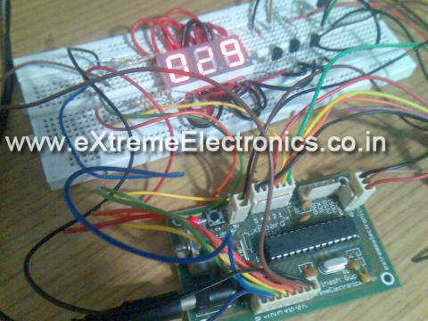 © 2011 Electroclub |


0 comments:
Post a Comment